Build an Audio Amplifier
Project description
This amplifier circuit provides excellent signal amplification and sound quality. In addition, this circuit has an extremely minimalistic design and can be built using only a few parts.
Parts list
-
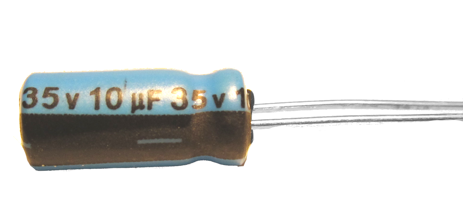
x2 10uf capacitor
-
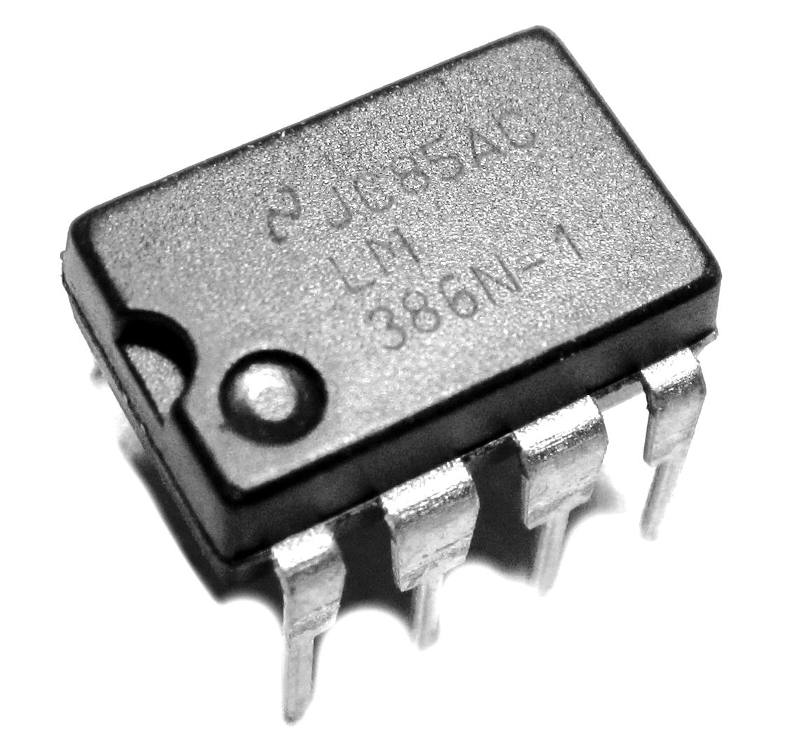
x2 LM386N-1
- x1 9V battery clip
- x1 9 Volt Battery Clip
- x1 9 Volt battery
- x1 8 to 16 Ohm speaker
-
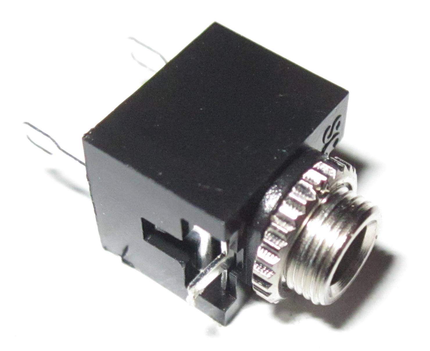
x1 3.5mm audio socket
- x1 4-pin connector & corresponding plug
-
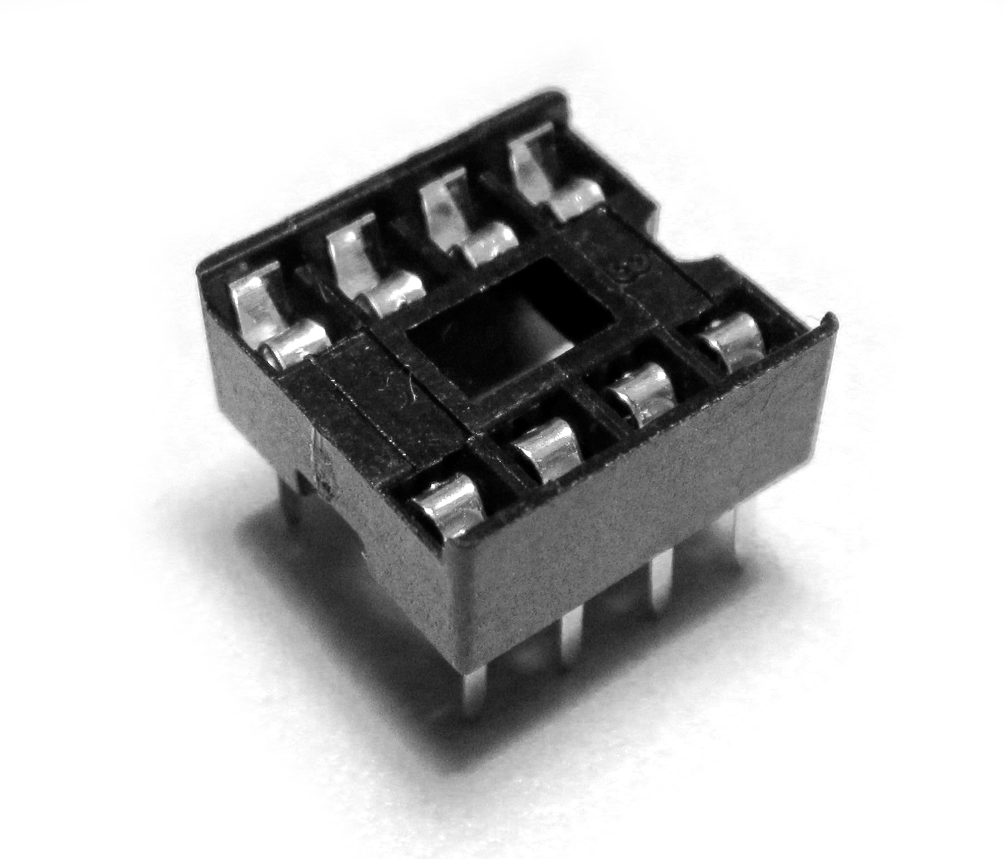
x1 8 pin IC socket
- x1 Speaker
-
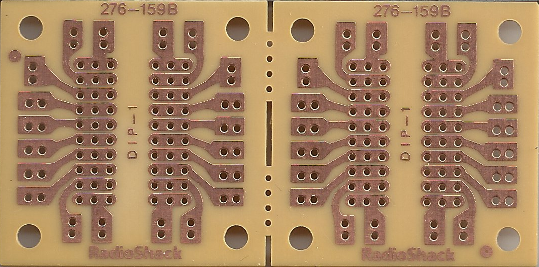
x1 PCB board
Tools
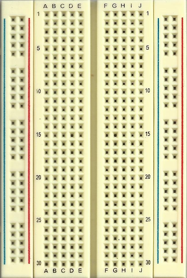
- Solderless breadboard
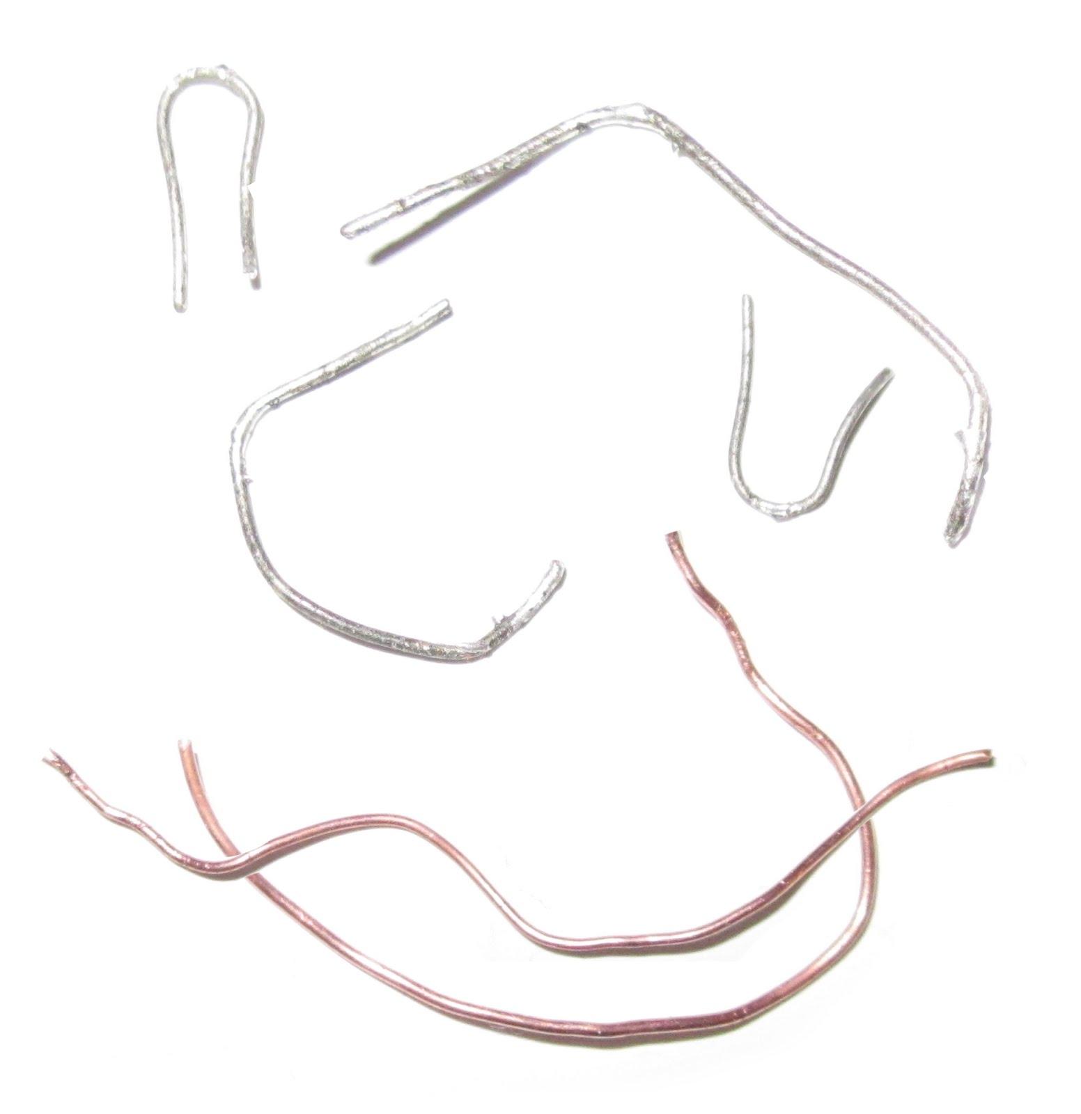
- Thin jumper wire
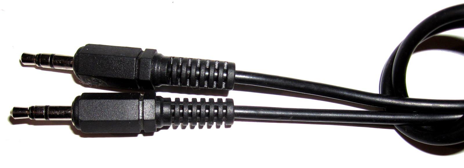
- 3.5 mm audio cable
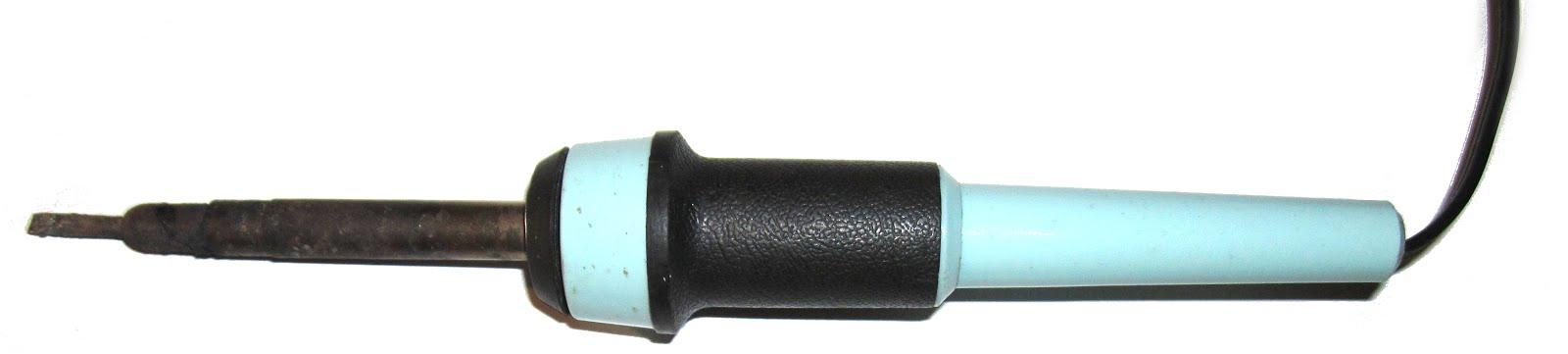
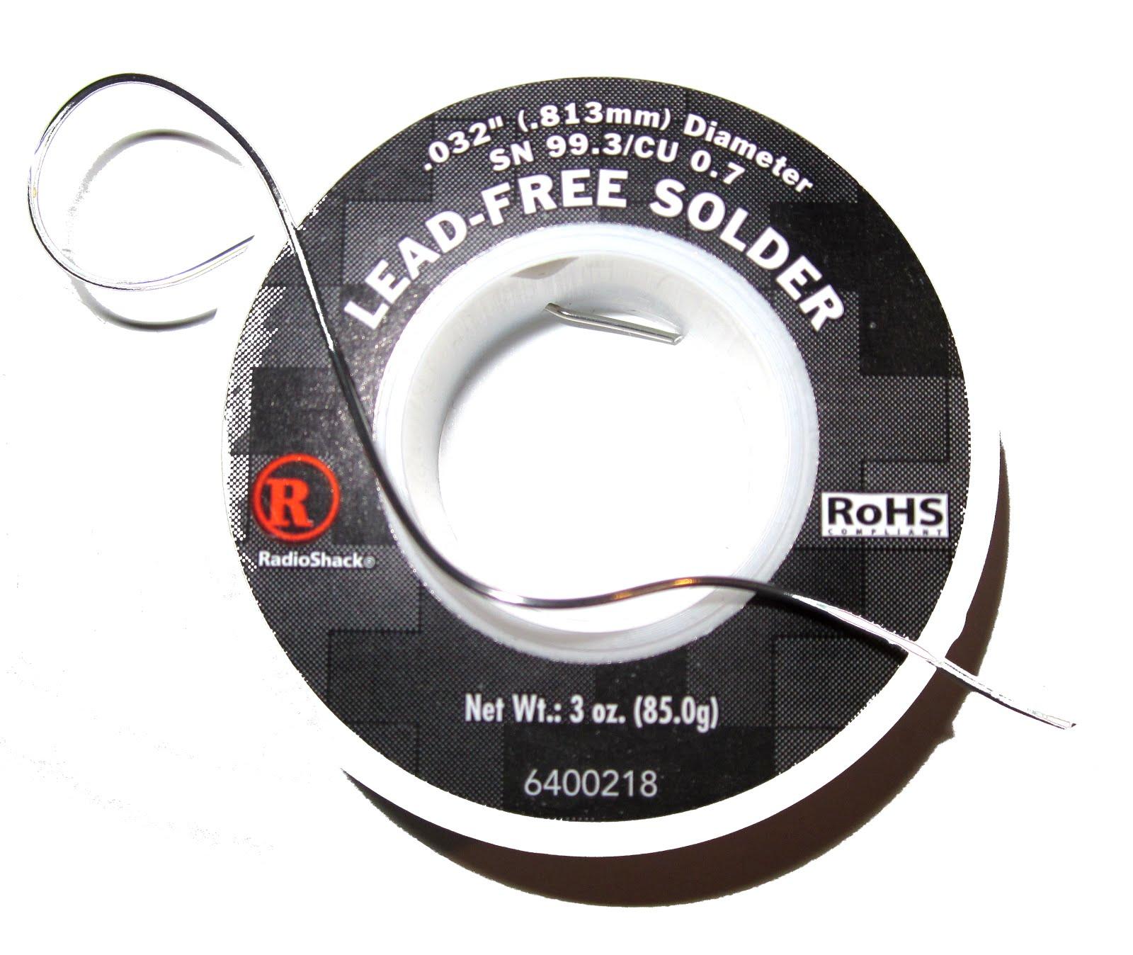
- Soldering iron & solder
- Pliers / Wire cutters
About the LM386N-1
How Integrated Circuit Pins are numbered:https://blog.salvius.org/2012/06/ics-integrated-circuits.html
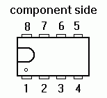
ICs will almost always have an indicator in the form of a small tab shape, circle or both on one side of the body to indicate the left side of the chip. With the pins facing down (live bug) and the indicator mark to the left you can count the pins. The pins start at 1 on the bottom left and count up as you go the the right. Then the top row starts counting on the right and goes to the left.
To build this amplifier we are using the LM386N-1 Audio Amplifier IC. This is a pretty usefull chip because it has low voltage requirements and an excellent amount of amplification. A good way to learn about this chip is to check out the data sheet which is available if you just do a search for "LM386N-1 datasheet" and you should find that there is plenty available from different manufacturers.
I'm using the Texas Instruments version of this sheet and they provide some useful hints down near the bottom of the sheet. They say: If a capacitor is put from pin 1 to 8, bypassing the 1.35 kΩ resistor, the gain will go up to 200 (46 dB).
So this is pretty useful because this tells us how we can increase the gain for this amplifier. The gain is just the amount that our amplifier increases the sound signal. By default LM386 chip has a gain of 20 but were going to increase that because we want to get as much out of this chip as we can.
Building the amplifier on a breadboard before soldering it together makes it easier to test for problems if it turns out that we made a mistake while building it.
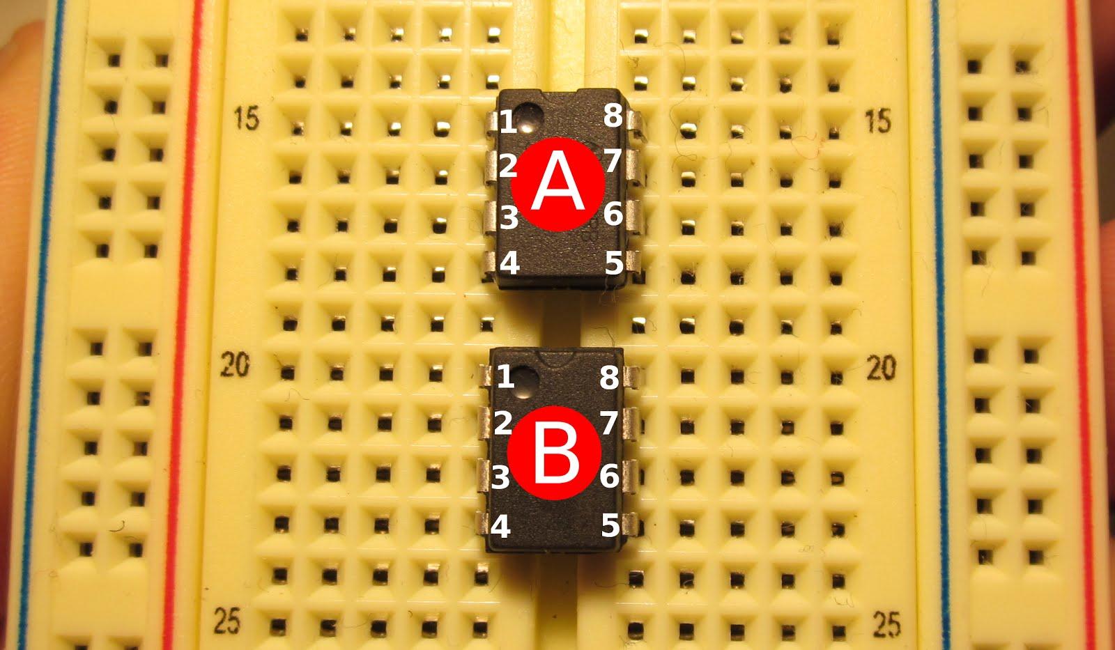
Begin by inserting the two ICs into the breadboard. The ICs in the photos have been labeled to make referencing them easier.
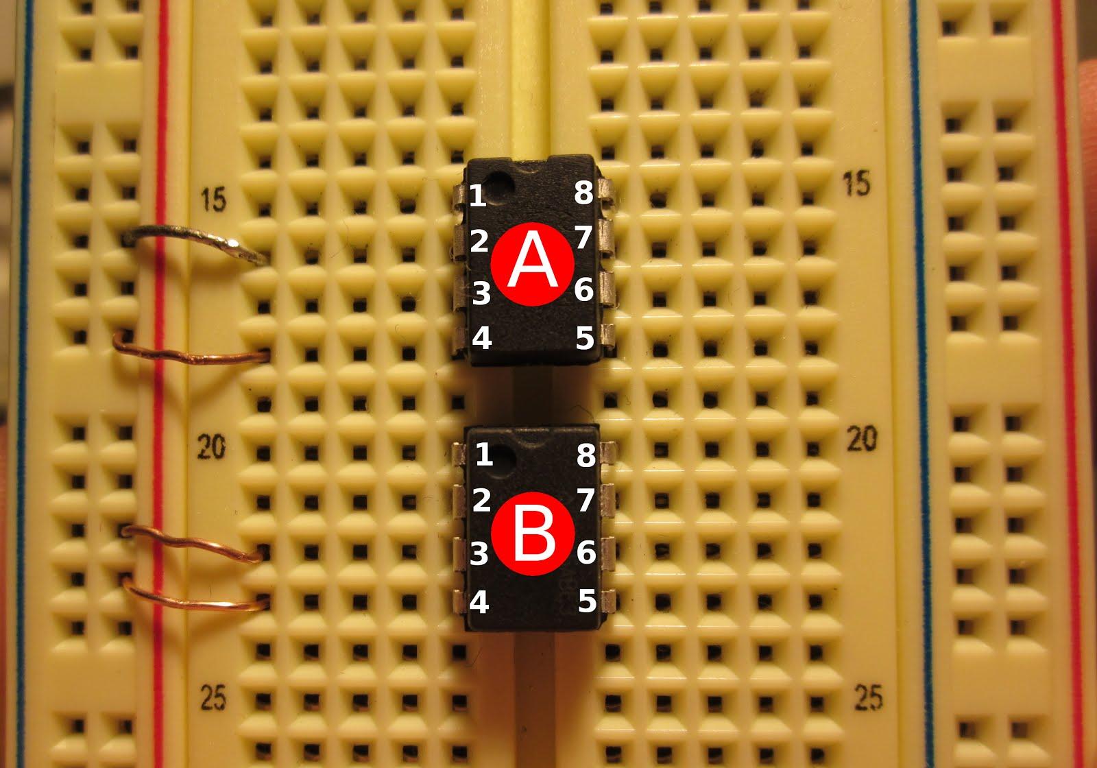
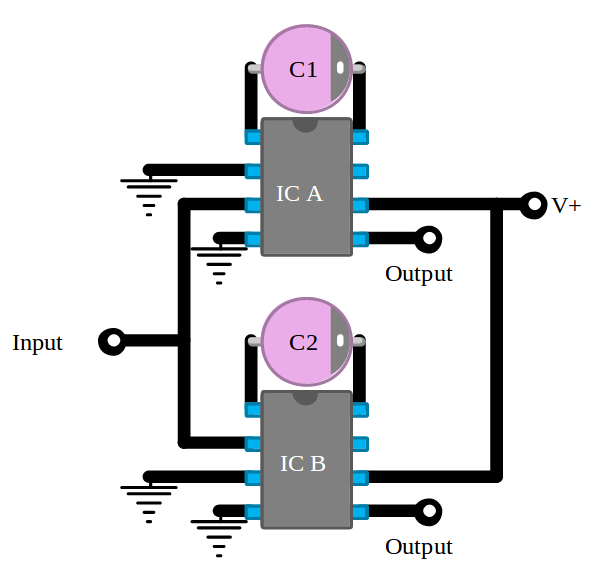
Connect pins 2 and 4 on IC A to the ground line. Connect pins 3 and 4 on IC B to the ground line.
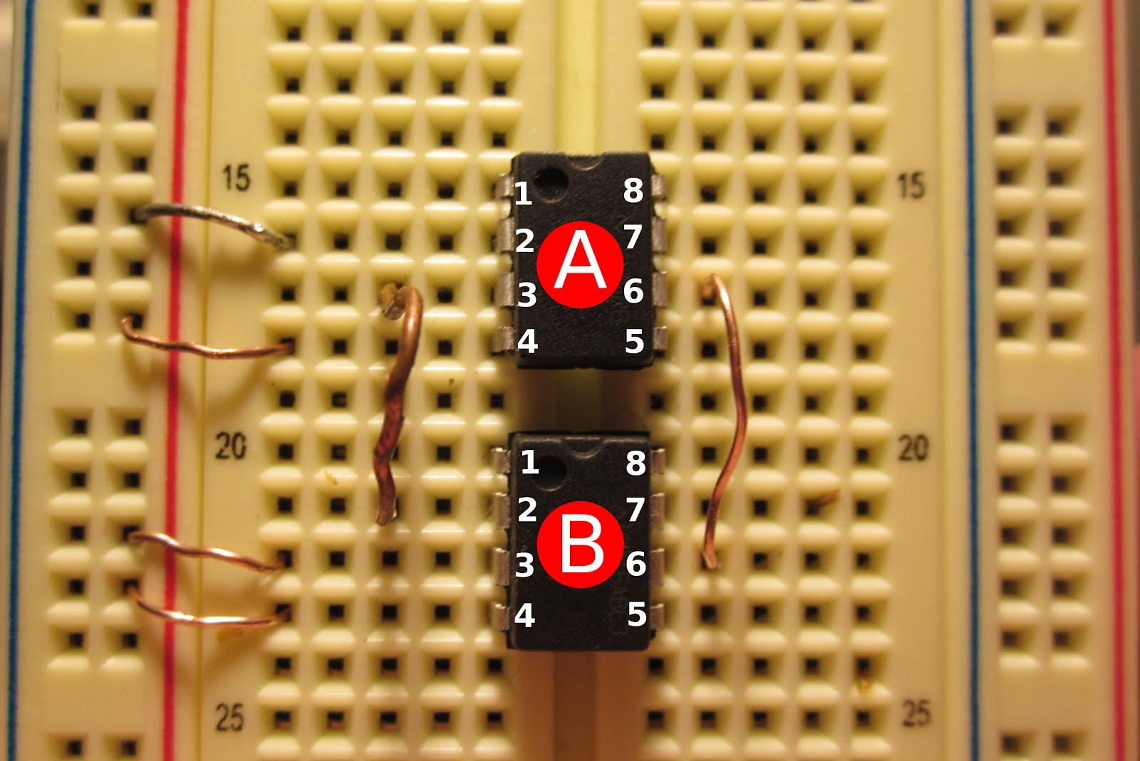
Connect pin 3 on IC A to pin 2 on IC B. Connect pin 6 on IC A to pin 6 on IC B.

Attach the 10 uf capacitors between pin 1 and 8 on each IC. Be sure to connect the negative side of the capacitor (stripe side) to pin 8.
Audio signal tester
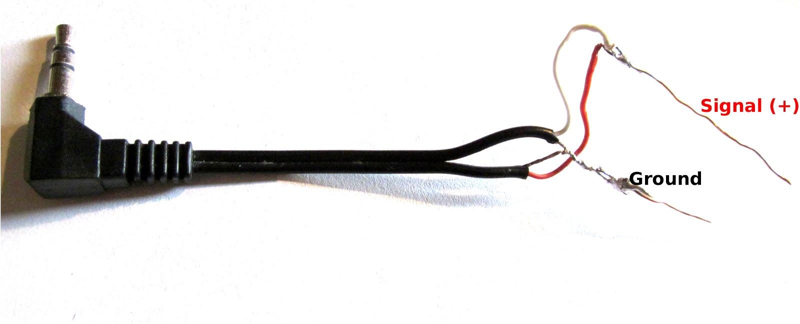
This is a tool you can make to test the breadboard. Use a cable from a pair of headphones and connect both pairs of ground and signal wires together as shown. Usually you can find a friend who has a broken pair to donate.
Connect the ground wire of the audio cable to the ground of your circuit. Attach the signal wire to pin 2 of IC B.
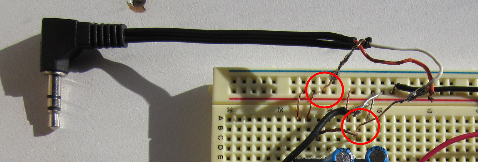
Connect the negative battery wire to ground and the positive wire to the pin 6 jumper.
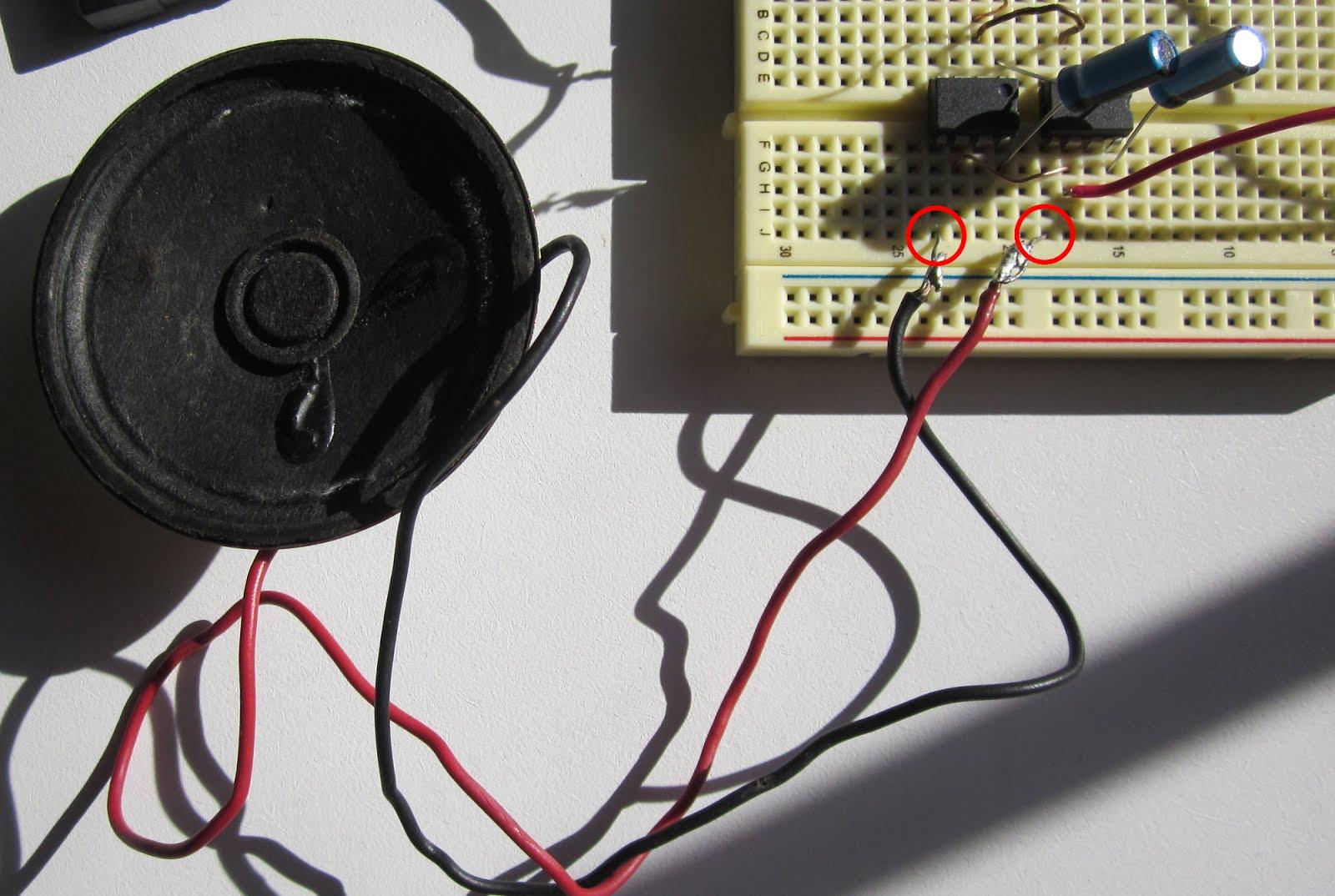
Connect the wire for the speaker between pin number 5 from both ICs.
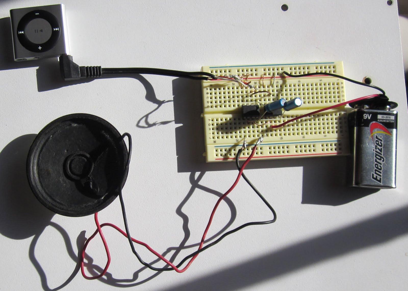
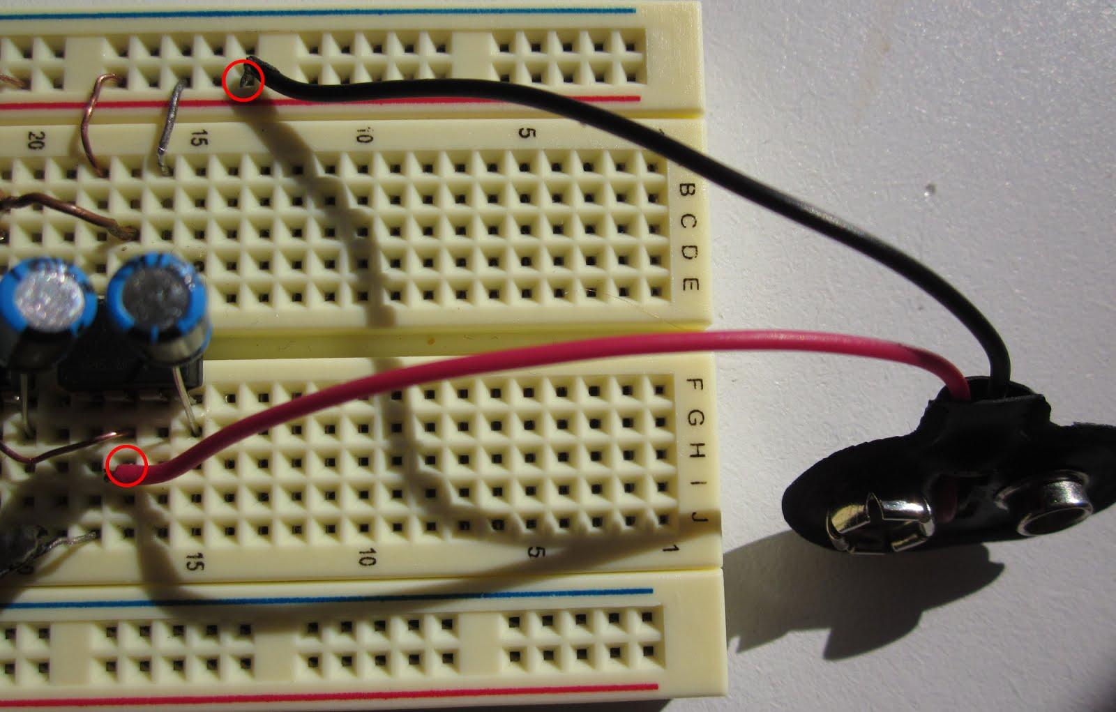
Testing the breadboard circuit
Connect the battery and plug in a radio or mp3 play to test your breadboard circuit. You should hear it working, if not go back and check to make sure that everything is connected correctly. If you have double checked your work and it is still not working it is possible that one of the ICs is not working. If that is the case, try switching it out with a new one.
Assembling the Amp
The next thing we are going to do is solder the parts onto a circuit board to make it permanent.
For this step I am going to also use a IC socket so that I can easily replace the ICs if I ever need to.
Separate the PCB pieces
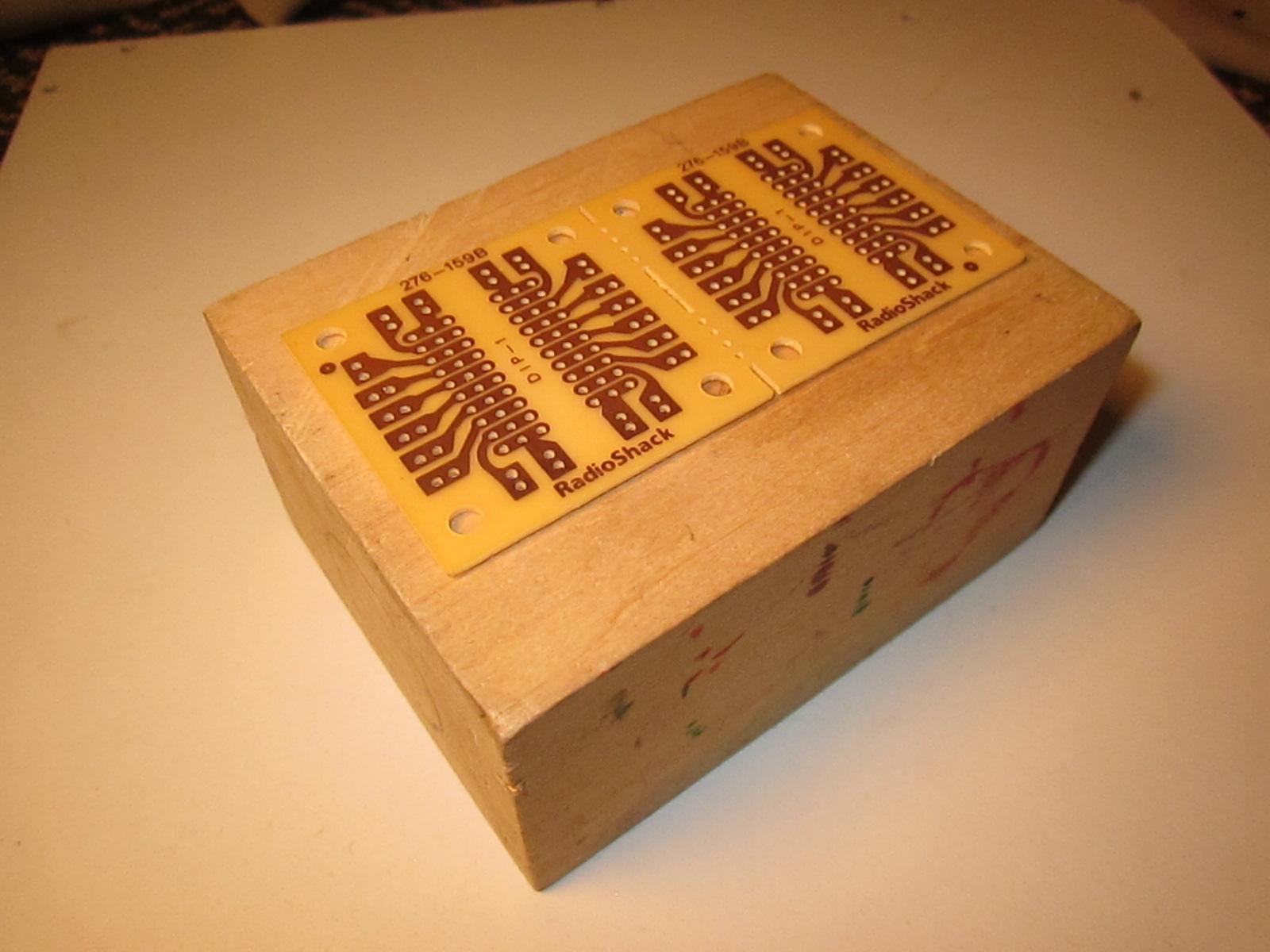
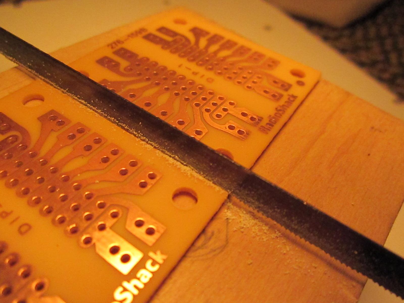
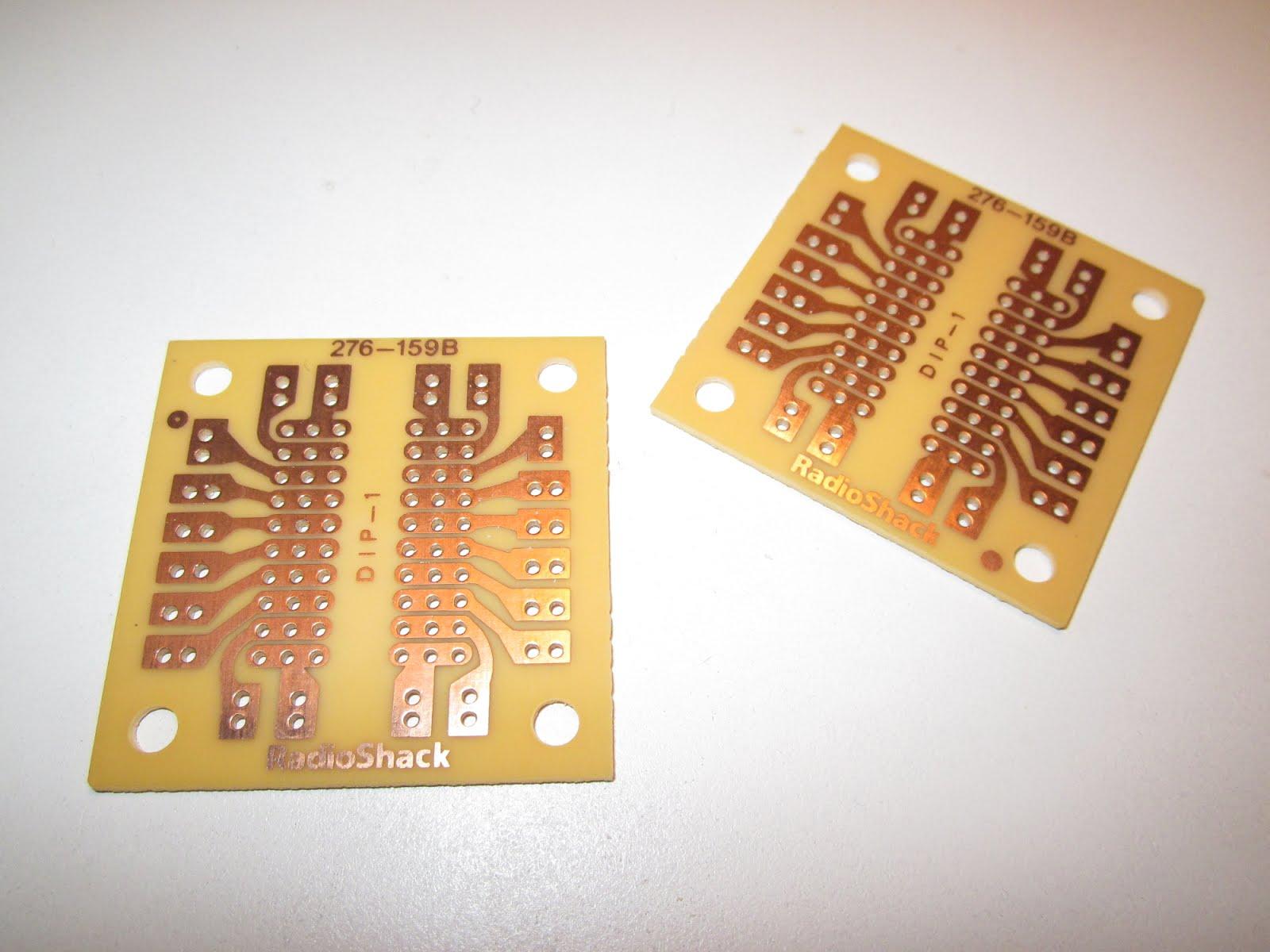
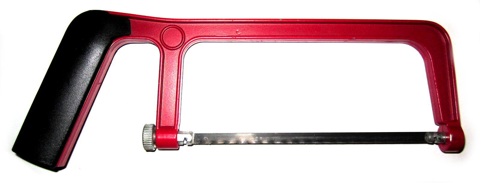
This PCB board comes with a perforated line down the center where you could probably snap the two pieces apart. A miter saw can be used to sever the thatching between the halves resulting in a cleaner edge. Use a block of wood to elevate the PCB board while you cut it.
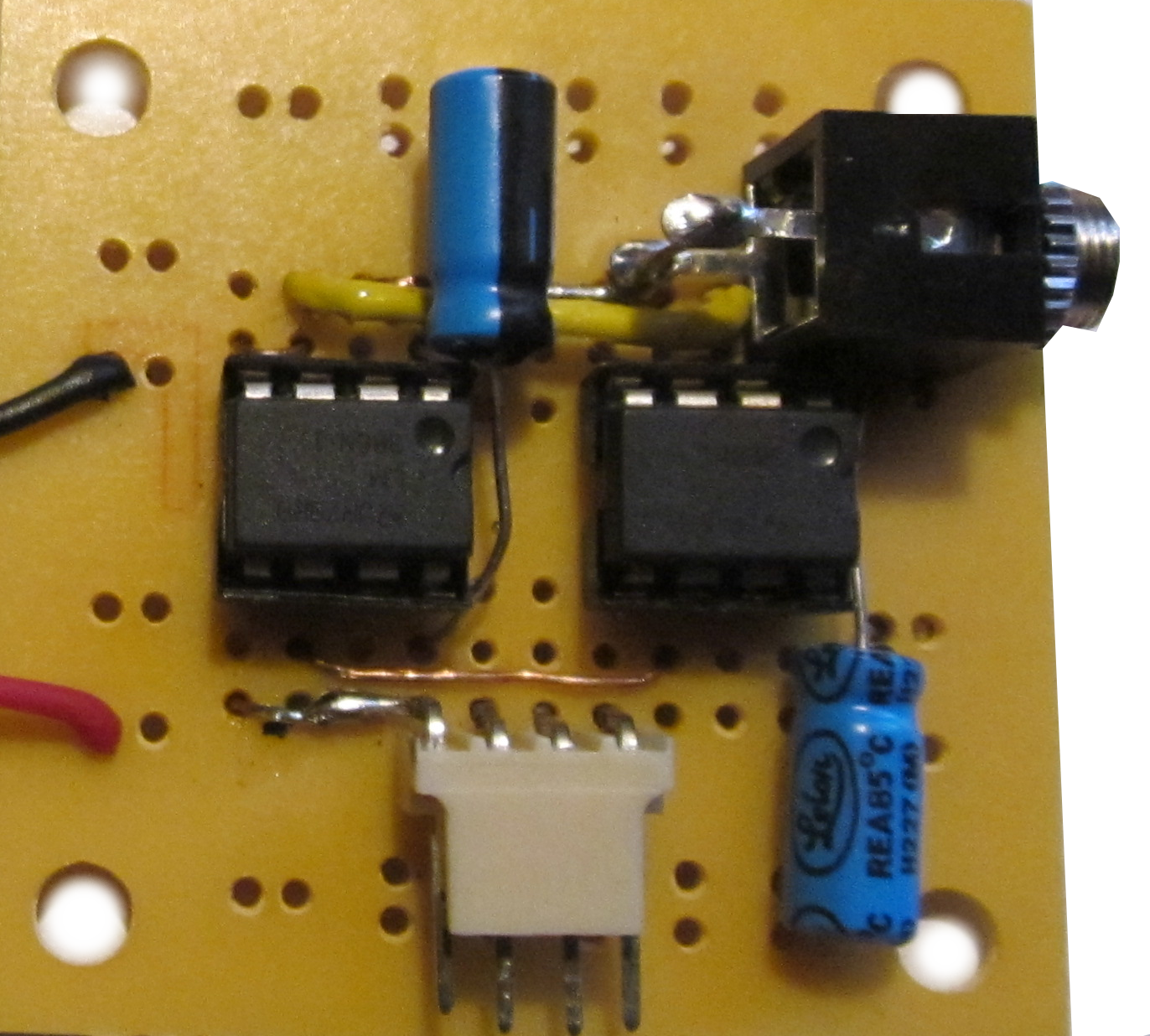
Assembling the Amp
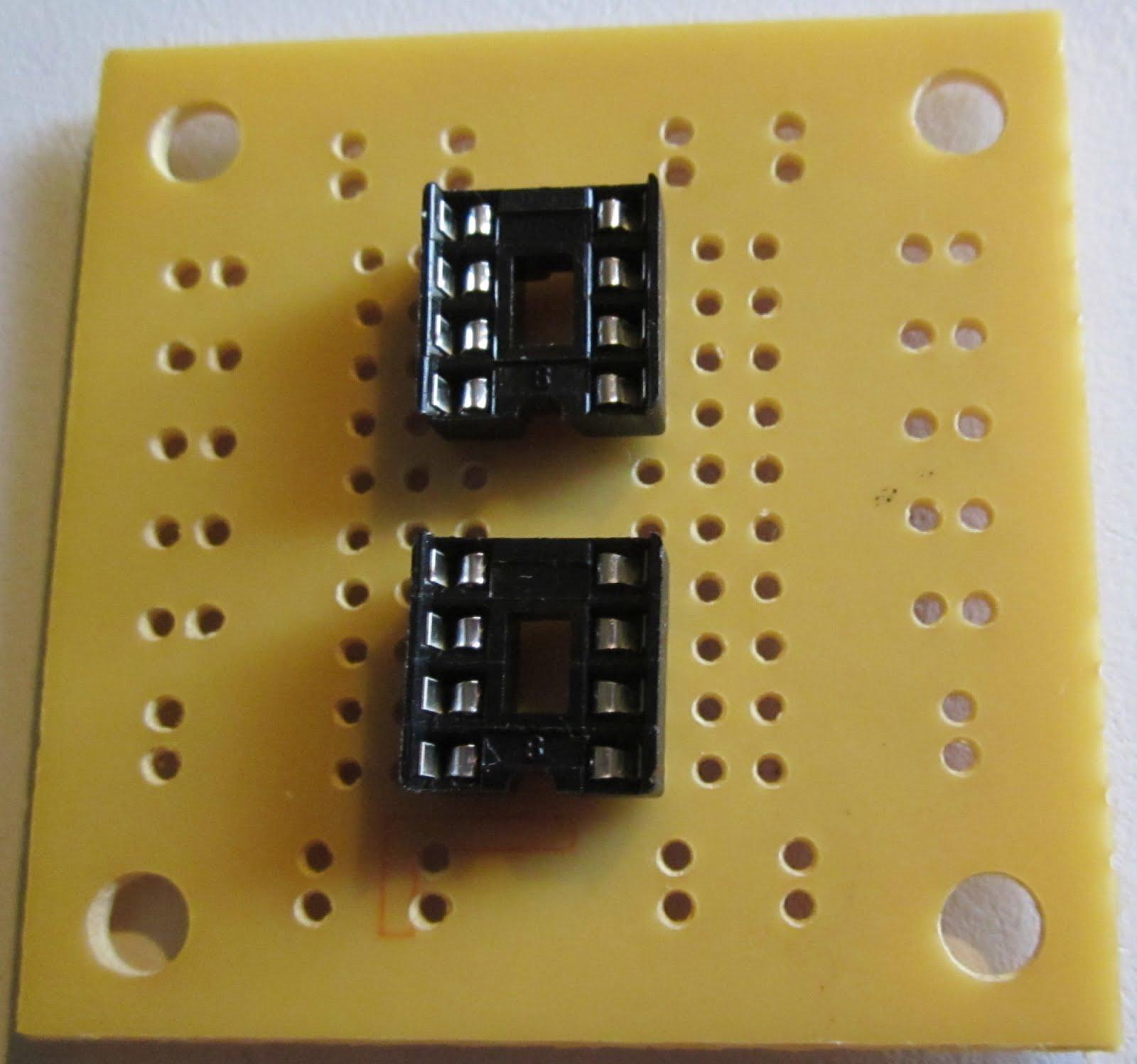
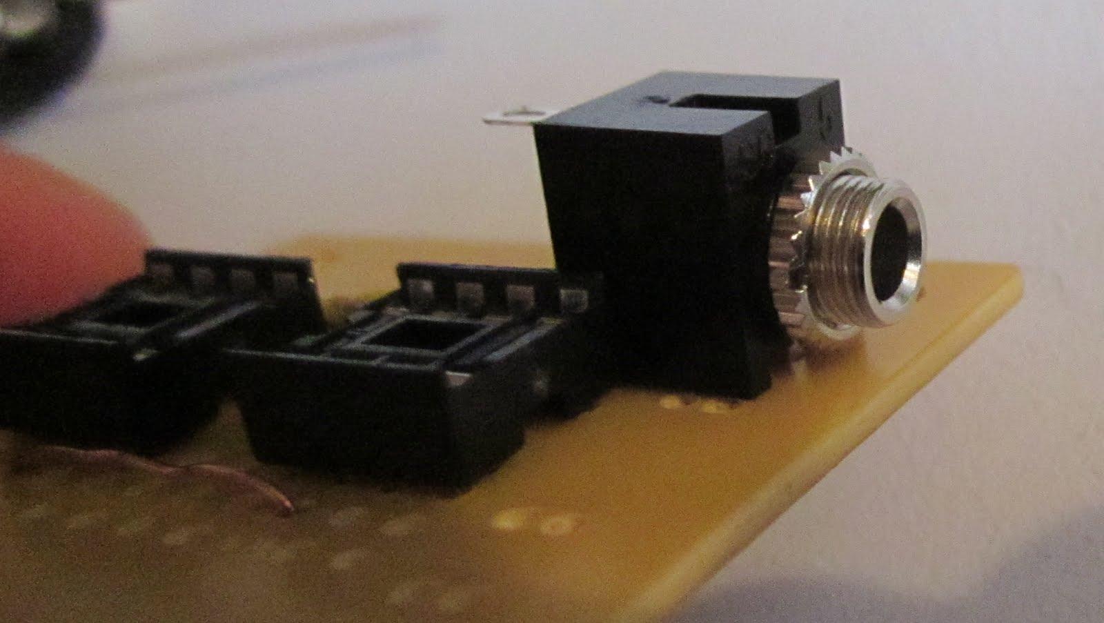
Place the pins of the IC sockets through the center holes of the PCB board. Flip the board over and apply solder to the base of each pin to hold the socket in place.
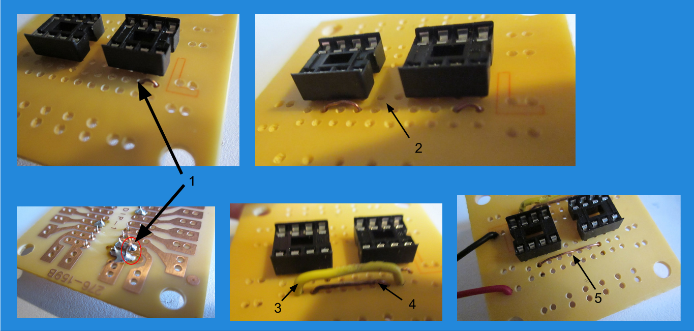
Solder in the five jumpers as shown. Refer back to the breadboard circuit for reference.
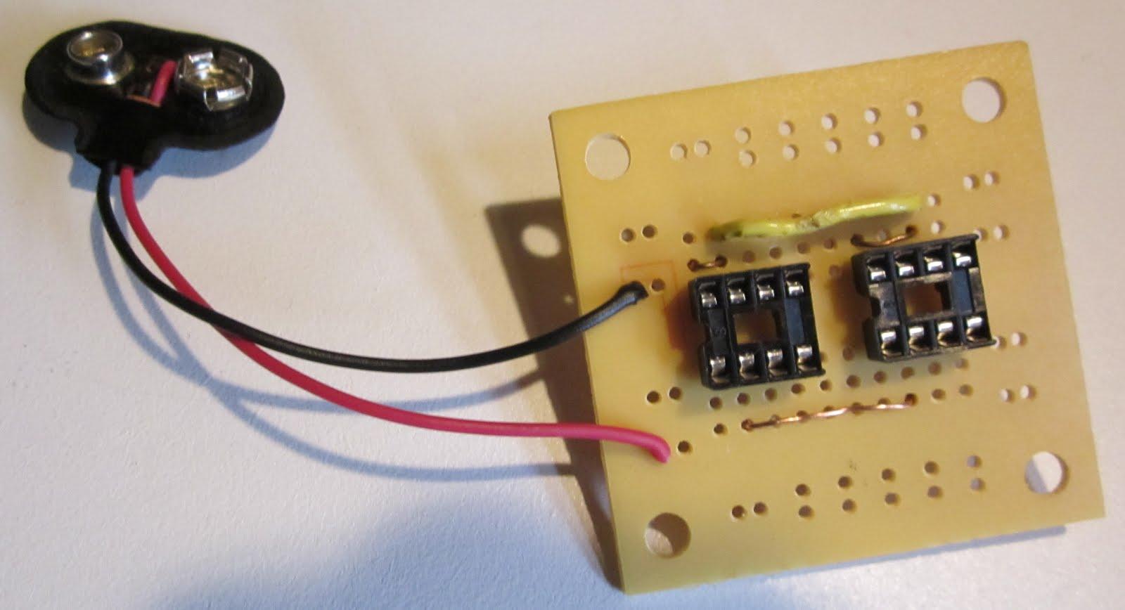
Solder the 9 volt battery clip to the board as shown.
Solder the 9 volt battery clip to the board as shown.
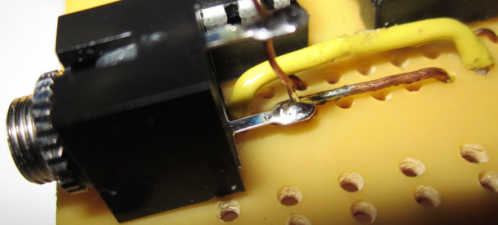
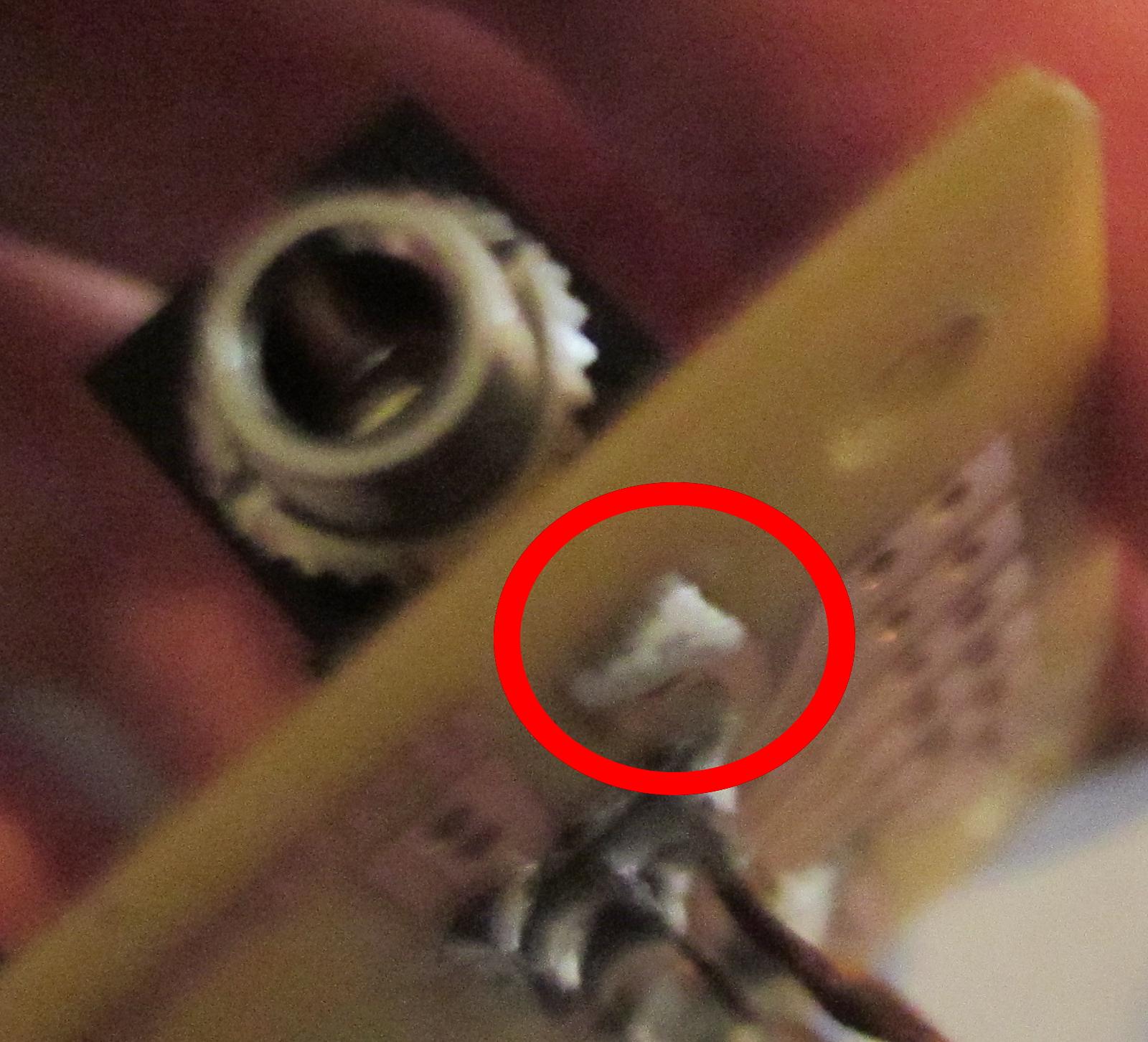
Solder a jumper wire across the two signal leeds of the audio jack. Make sure that this jumper is also soldered to the jumper between IC A pin 3 and IC B pin 2. The points you must solder have been indicated in the photo.
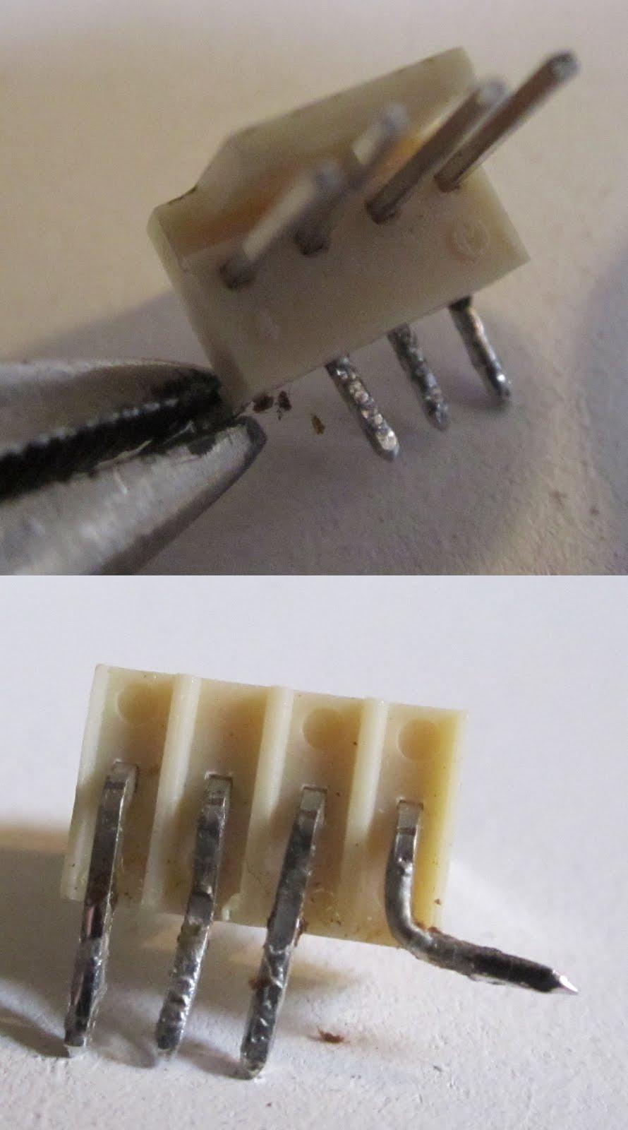
Use a pair of pliers to bend the bottom right connector pin at a 90 degree angle.
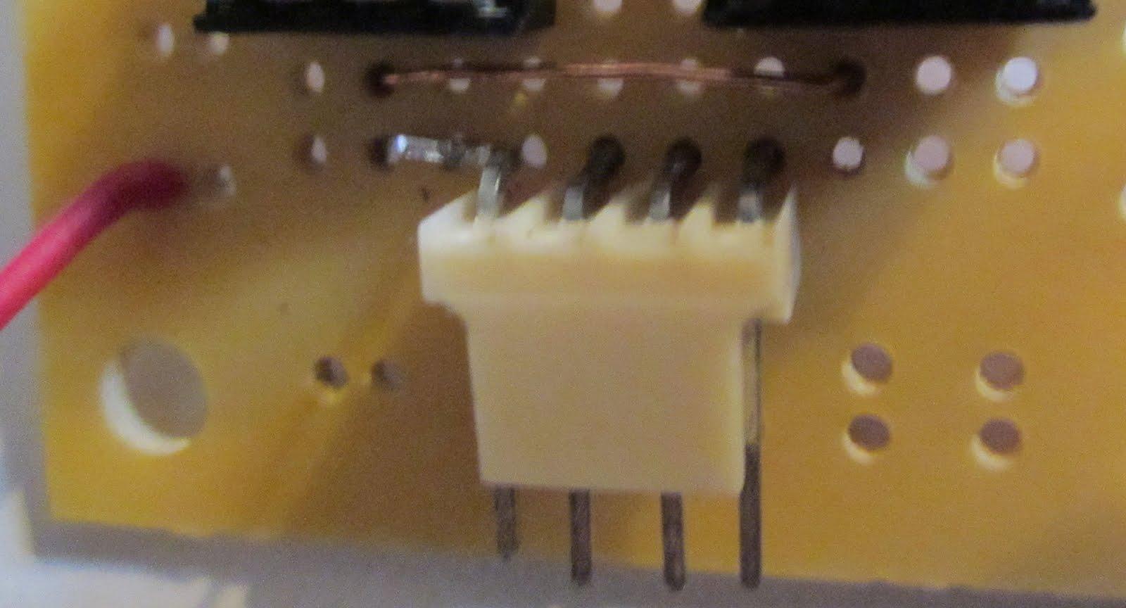
Insert the connector into the PCB board so that the left pin can be soldered to pin 5 of IC A.
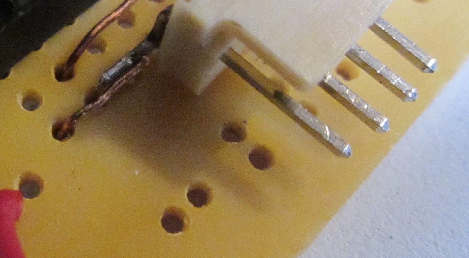
Solder a jumper from pin 5 of IC B to the bent pin of the connector.
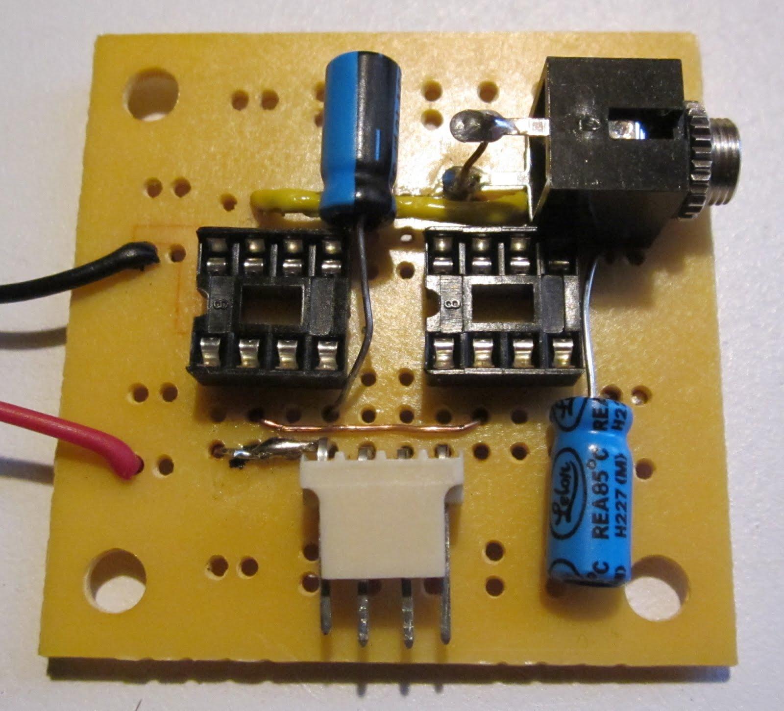
Solder the two 10 uF capacitors between pins 1 and 8 on each IC. Be sure to position the negative polarity indicator on the capacitor on pin 8.
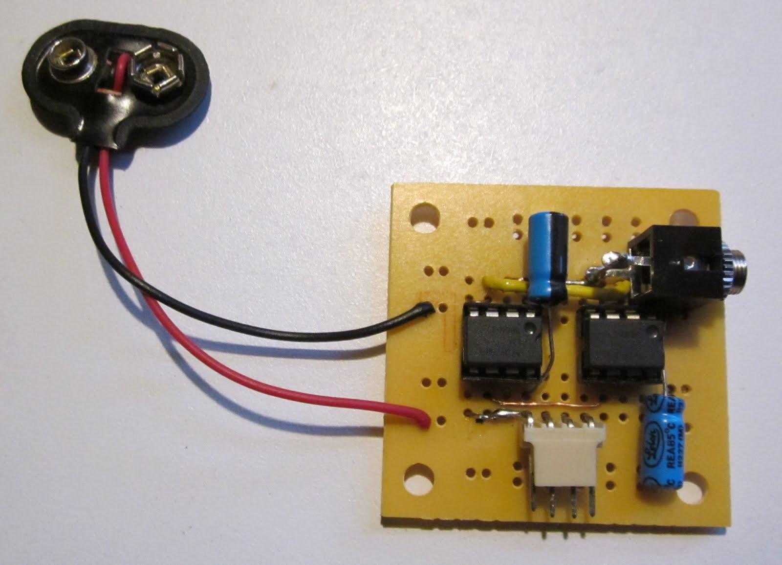
Trim off any excess wire and then insert the ICs into the sockets. You must insert them with the polarity indicator facing the right way as shown. Plug in an mp3 player or a laptop through the audio jack and test it out. Plug your speaker into the four pin socket.