Bipedal modality provides an efficient and versatile form of locomotion that allows robots to excel in human environments. However, bipedal walking is one of the most challenging aspects of humanoid robotics, requiring sophisticated balance control, coordinated multi-joint movement, and real-time stability management. This specification covers both static walking approaches (always maintaining balance) and dynamic walking methods (controlled falling).

Design Philosophy and Challenges

Why Bipedal Locomotion?

  • Human Environments: Stairs, narrow passages, and spaces designed for two-legged beings
  • Height Advantage: Reach objects at human heights, interact at eye level
  • Efficient in Constrained Spaces: Smaller footprint than wheeled or quadruped designs
  • Tool Use: Frees upper limbs for manipulation tasks
  • Aesthetic: More human-like appearance and interaction

Fundamental Challenges

  • Inherent Instability: Two-point contact provides minimal stability
  • Complex Dynamics: Inverted pendulum system requires constant correction
  • Energy Intensive: Requires significant power for balance and movement
  • Control Complexity: Must coordinate 6-12 DOF in real-time
  • Mechanical Stress: High loads on joints, especially during impacts
Important Note: Many successful humanoid robots use wheeled bases or static platforms instead of true bipedal walking. Consider whether full walking capability is necessary for your application, or if a simpler mobility solution would suffice.

Overview

Leg Joint Placement and Degrees of Freedom
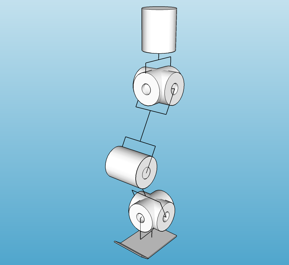
Humanoid robot legs showing degrees of freedom at hip, knee, and ankle joints

A minimal bipedal walking system requires 6 degrees of freedom (DOF) per leg, distributed across three major joint complexes:

Joint Complex DOF Movement Types Primary Function
Hip 3 Flexion/Extension, Abduction/Adduction, Rotation Leg positioning, lateral balance
Knee 1 Flexion/Extension Leg length adjustment, shock absorption
Ankle 2 Dorsiflexion/Plantarflexion, Inversion/Eversion Ground contact, balance fine-tuning
Total per leg 6 Total system: 12 DOF for both legs

Simplified Configurations

For static walking or limited mobility, the DOF count can be reduced:

  • 4 DOF per leg: Remove hip rotation and ankle inversion/eversion (can walk forward/backward on flat ground)
  • 3 DOF per leg: Remove ankle joints entirely (static standing, limited walking)
  • 2 DOF per leg: Hip flexion and knee only (sitting/standing transitions, not walking)

Range of Movement

Joint Movement Human Range Robot Minimum Robot Recommended
Hip Flexion/Extension 120° / 20° 90° / 10° 120° / 30°
Abduction/Adduction 45° / 30° 20° / 10° 45° / 30°
Internal/External Rotation 45° / 45° 0° (fixed) 30° / 30°
Knee Flexion/Extension 135° / 0° 90° / 0° 130° / 0°
Ankle Dorsiflexion/Plantarflexion 20° / 50° 10° / 20° 20° / 45°
Inversion/Eversion 35° / 15° 0° (fixed) 20° / 20°

Note: Flexion angles are from neutral standing position. Greater range enables more natural gait but increases mechanical complexity.

Dimensions, Weight and Center of Gravity

Proportional Scaling

Human leg proportions follow consistent ratios. For a robot with total height H:

Segment Proportion of Height (H) Example (H = 1.5m)
Total Leg Length 0.50 - 0.53 H 750-795 mm
Thigh (Hip to Knee) 0.25 H 375 mm
Shin (Knee to Ankle) 0.25 H 375 mm
Foot Length 0.15 H 225 mm
Hip Width 0.19 H 285 mm

Center of Gravity Considerations

  • Standing Position: CoG should be ~55-60% of total height from ground
  • Weight Distribution: Lower body should be 40-50% of total robot weight
  • Battery Placement: Heavy batteries best placed low in torso or upper legs to lower CoG
  • Foot Size: Larger feet provide more stability but reduce maneuverability
Stability Rule: The robot's center of gravity projection must remain within the support polygon (foot contact area) for static stability. During walking, predictive control is needed for dynamic stability.

Functional Requirements

The hip is the most complex joint in the leg, requiring three degrees of freedom to position the leg in 3D space. It must support the entire weight of the robot during single-leg stance while walking, making it the highest-stress joint in the system.

Three-Axis Hip Design

Most successful humanoid robots use three perpendicular rotation axes at the hip:

  • Yaw (Hip Rotation): Allows leg to rotate about vertical axis
  • Roll (Abduction/Adduction): Moves leg away from or toward centerline
  • Pitch (Flexion/Extension): Swings leg forward and backward

Servo Configuration

Axis Mounting Torque Requirements Critical Notes
Yaw (Rotation) Vertical shaft in pelvis LOW (10-20 kg·cm) Least stressed, can use smaller servo
Roll (Abduction) Horizontal, perpendicular to leg HIGH (40-80 kg·cm) Supports full leg weight laterally
Pitch (Flexion) Horizontal, parallel to hips VERY HIGH (60-120 kg·cm) Highest stress during walking

Construction Methods

Method 1: Sequential Servo Mount

  • Each servo mounts to the previous servo's horn/bracket
  • Creates a chain: pelvis → yaw servo → roll servo → pitch servo → thigh
  • Advantages: Simple concept, easy to visualize and build
  • Disadvantages: Heavy and bulky, each servo must support weight of subsequent servos
  • Best For: Smaller robots (under 50cm tall), prototypes

Method 2: Parallel Mounting Frame

  • All three servos mount to a rigid frame structure
  • Linkages connect servos to thigh mount point
  • Advantages: More compact, better load distribution
  • Disadvantages: Complex mechanical design, requires precise fabrication
  • Best For: Medium to large robots, final production designs

Method 3: Spherical Joint Mechanism

  • Ball-and-socket joint provides 3-DOF in single mechanical element
  • Actuators drive the joint via cables or external linkages
  • Advantages: Compact, wide range of motion
  • Disadvantages: Very complex to design and build, difficult to control
  • Best For: Advanced projects, research platforms

Torque Calculations

To size hip servos, calculate the torque required to support the leg:

Hip Pitch (Forward/Back) Torque:
T = (Mleg × Lleg × g) + safety_factor

Where:
• Mleg = mass of leg (kg)
• Lleg = distance from hip to leg center of mass (m)
• g = gravitational acceleration (9.81 m/s²)
• safety_factor = 2.0-3.0 for dynamic movement
• T = required torque (N·m)

Example: 2kg leg, CoM at 20cm, safety factor 2.5
T = (2 × 0.2 × 9.81) × 2.5 = 9.81 N·m = 100 kg·cm
Hip Roll (Abduction) Torque:
T = (Mrobot × Dhip-width × g) + safety_factor

Where:
• Mrobot = total robot mass (kg)
• Dhip-width = distance from hip joint to CoG centerline (m)
• During single-leg stance, this servo supports entire robot weight

Servo Motor Evaluation

Robot Height Total Mass Hip Pitch/Roll Servo Hip Yaw Servo
150+ cm 40+ kg Industrial servo with 10:1+ gearbox (300+ kg·cm) Dynamixel MX-64 or industrial servo

Mechanical Considerations

  • Bearing Support: Use ball bearings at high-load pivot points to reduce servo stress
  • Hard Stops: Implement mechanical stops to prevent over-rotation and protect servos
  • Shock Absorption: Consider rubber dampers at hip mounts to reduce impact transmission
  • Cable Management: Hip joints have complex wiring; plan cable routing carefully
  • Heat Dissipation: Hip servos work hardest; ensure good ventilation

Functional Requirements

The knee is a single degree of freedom hinge joint connecting the thigh and shin. Despite being simpler than the hip, it experiences extremely high loads during walking and must be robust enough to support the full weight of the robot during stance phase.

Key Functions

  • Leg Length Adjustment: Allows robot to lower/raise center of mass
  • Swing Phase Clearance: Bends to lift foot off ground during walking
  • Shock Absorption: Flexes to cushion impacts when foot contacts ground
  • Energy Storage: Can store elastic energy during gait (with spring elements)

Movement Range

  • Minimum: 0° (straight leg) to 90° (bent)
  • Recommended: 0° to 130° for natural gait and sitting
  • No Hyperextension: Must not bend backward beyond 0°

Construction Methods

Method 1: Direct Servo Hinge

  • Servo mounts at knee with shaft axis perpendicular to leg
  • Thigh and shin connect directly to servo body and horn
  • Advantages: Simplest possible design, minimal parts
  • Disadvantages: Servo bears all lateral loads, limited to lighter robots
  • Best For: Small robots (under 3kg), prototypes

Method 2: Bearing-Supported Hinge

  • Main load-bearing shaft runs through bearings in thigh and shin
  • Servo connects via gear or linkage to drive shaft
  • Advantages: Bearings handle lateral loads, servo only provides torque
  • Disadvantages: More complex, requires precision machining
  • Best For: Medium to large robots, production designs

Method 3: Four-Bar Linkage

  • Parallel linkage system creates virtual hinge point
  • Distributes loads across multiple pivot points
  • Advantages: Very strong, even load distribution
  • Disadvantages: Bulky, complex geometry
  • Best For: Heavy-duty applications, large robots

Torque Requirements

Knee Torque Calculation:
T = (Mshin+foot × Lshin × g) × safety_factor

Where:
• Mshin+foot = combined mass of shin and foot (kg)
• Lshin = shin length from knee to CoM (m)
• safety_factor = 2.0-2.5 for walking

Example: 1kg shin+foot, 20cm length, factor 2.0
T = (1 × 0.2 × 9.81) × 2.0 = 3.92 N·m = 40 kg·cm

Note: Knee torque is typically lower than hip torque since it only supports the lower leg, not the entire robot.

Mechanical Design Details

Hyperextension Prevention

  • Mechanical Stop: Hard stop at 0° prevents backward bending
  • Locking Mechanism: Optional ratchet or pin locks knee straight for standing
  • Software Limits: Set servo endpoints to prevent overextension

Shock Absorption

  • Compliance: Add rubber bushings at pivot points
  • Spring Elements: Parallel springs can store/release energy during gait
  • Dampers: Small dampers prevent oscillation after impact

Weight Reduction

  • Use hollow tubes for shin structure
  • Aluminum or carbon fiber preferred over steel
  • Place heavy components (batteries) in upper body, not lower leg

Functional Requirements

The ankle joint connects the leg to the foot and provides critical balance control during standing and walking. It acts as the final adjustment point between the robot's center of mass and the ground contact surface.

Two-Axis Ankle (Recommended)

  • Pitch (Dorsiflexion/Plantarflexion): Foot tilts up/down, essential for walking
  • Roll (Inversion/Eversion): Foot tilts side-to-side, crucial for balance on uneven ground

Movement Ranges

Axis Movement Minimum Range Recommended Range
Pitch Dorsiflexion (up) 10° 20°
Pitch Plantarflexion (down) 20° 45°
Roll Inversion/Eversion 0° (fixed) ±20°

Simplified Ankle Designs

Single-Axis Ankle (Pitch Only)

  • One servo provides pitch (forward/back tilt)
  • Sufficient for walking on flat surfaces
  • Simpler control and construction
  • Roll stability must come from hip control

Passive Ankle

  • No actuators; foot connected with compliant material (springs, rubber)
  • Provides passive shock absorption
  • Extremely simple and lightweight
  • Limited to very basic walking or static standing

Fixed Ankle

  • Foot rigidly attached to shin
  • Simplest possible configuration
  • Can achieve static standing and limited shuffling
  • Not suitable for dynamic walking

Construction Methods

Two-Servo Perpendicular Mount

  • Pitch servo connects shin to intermediate bracket
  • Roll servo connects bracket to foot
  • Servos oriented 90° to each other
  • Simple and effective for most robots

Universal Joint with Actuators

  • U-joint provides 2-DOF passive movement
  • Servos control joint via cables or linkages
  • More compact than direct servo mount
  • Complex mechanical design

Torque Requirements

Ankle Pitch Torque:
T = (Mrobot × DCoG-to-ankle × g) × safety_factor

During walking, ankle must support entire robot weight moments
Typically requires 30-50% of hip pitch torque

Ankle Roll Torque:
Similar to ankle pitch but typically slightly less
Can use same size servo for both axes

Foot Design Principles

The foot is the only point of contact between robot and ground. Its design directly impacts stability, balance, and walking performance. Larger feet provide more stability but reduce maneuverability and increase the risk of foot-ground interference.

Human foot anatomical structure showing bones and arch

Key Design Parameters

Parameter Typical Range Impact
Length 15-20% of robot height Longer = more stable, but harder to maneuver
Width 40-50% of foot length Wider = more lateral stability
Thickness 20-40mm Thicker allows sensors, wiring space
Surface Material Rubber, foam, textured High friction prevents slipping

Foot Construction Approaches

Flat Plate Foot (Simplest)

  • Design: Rectangular or foot-shaped flat plate
  • Materials: Plywood, acrylic, 3D printed plastic, aluminum
  • Base Material: Rubber sheet adhered to bottom for friction
  • Advantages: Extremely simple, large support polygon
  • Disadvantages: Cannot conform to uneven ground
  • Best For: Beginners, indoor flat-surface walking

Multi-Contact Foot

  • Design: Multiple separate pads at toe and heel
  • Contact Points: Typically 3-4 points (heel, ball, toes)
  • Advantages: Better sensing, can detect contact points separately
  • Disadvantages: More complex, requires multiple sensors
  • Best For: Advanced walking, force-controlled gait

Compliant/Flexible Foot

  • Design: Rigid structure with flexible sole (foam, rubber)
  • Compliance: Foot deforms to conform to ground irregularities
  • Advantages: Passive shock absorption, better grip on uneven surfaces
  • Disadvantages: Harder to model dynamics, can wear out
  • Best For: Outdoor use, rough terrain

Articulated Foot (Advanced)

  • Design: Toe section can bend separately from foot
  • Actuation: Additional servo for toe flexion
  • Advantages: Can "push off" with toes like human gait
  • Disadvantages: Adds DOF and complexity
  • Best For: Research, high-performance humanoids

Sensing and Feedback

Force Sensitive Resistors (FSR)

  • Place at heel and toe (minimum) or 4-6 points across foot
  • Detect when foot contacts ground and weight distribution
  • Essential for gait phase detection
  • Inexpensive and simple to integrate

Pressure Mat Arrays

  • Grid of sensors shows pressure distribution
  • High-resolution data for balance control
  • Expensive and complex to process
  • Used in advanced research platforms

Contact Switches

  • Simple binary detection (foot on ground: yes/no)
  • Microswitches or limit switches at foot edges
  • Minimal cost and complexity
  • Sufficient for basic walking

IMU in Foot

  • Accelerometer/gyroscope detects foot motion and orientation
  • Can detect impacts, foot angle, acceleration
  • Useful for gait analysis and control refinement

Center of Pressure (CoP) and Zero Moment Point (ZMP)

Understanding where forces act on the foot is critical for balance:

  • Center of Pressure (CoP): The point on the foot where ground reaction force acts
  • Zero Moment Point (ZMP): Point where horizontal moment equals zero
  • Stability Criterion: ZMP must remain within foot support polygon for stability
  • Sensor Requirement: Multiple force sensors allow CoP calculation
Control Strategy: Advanced walking controllers continuously adjust joint positions to keep ZMP within safe bounds. This requires real-time sensor feedback and fast control loops (100+ Hz).

Static Walking (Beginner-Friendly)

Principle

Robot maintains static balance at all times by ensuring center of gravity always projects within support polygon. Walking is achieved through a sequence of stable poses.

Walking Sequence

  1. Shift Weight: Move CoG over one leg (stance leg)
  2. Verify Balance: Ensure CoG projection is within stance foot
  3. Lift Swing Leg: Raise other leg off ground
  4. Move Swing Leg Forward: Position leg for next step
  5. Lower Swing Leg: Place foot on ground
  6. Transfer Weight: Shift CoG to new position over both feet
  7. Repeat: Alternate legs

Advantages

  • Never falls (if executed correctly)
  • Simple to understand and implement
  • No complex dynamics calculations required
  • Can pause at any point in gait

Disadvantages

  • Very slow walking speed
  • Energy inefficient (constant lifting of CoG)
  • Unnatural, robotic appearance
  • Large feet required for stability

Dynamic Walking (Advanced)

Principle

Robot uses momentum and controlled falling to achieve faster, more efficient walking. The center of gravity may move outside the support polygon during swing phase, with stability maintained dynamically.

Control Approaches

ZMP-Based Control

  • Plans trajectory to keep Zero Moment Point within support polygon
  • Most common method for humanoid robots (ASIMO, Atlas, etc.)
  • Requires inverse kinematics and dynamics calculations
  • Computationally intensive but stable

Inverted Pendulum Model

  • Models robot as simple inverted pendulum
  • Uses linear approximations for fast computation
  • Good for flat terrain at moderate speeds
  • Foundation for Model Predictive Control (MPC)

Passive Dynamic Walking

  • Exploits natural dynamics; minimal actuation
  • Very energy efficient
  • Limited to specific conditions (downhill slope, specific leg design)
  • Research topic more than practical solution

Learning-Based Control

  • Machine learning algorithms (reinforcement learning, neural networks)
  • Can discover novel gaits and adapt to terrain
  • Requires extensive training and powerful hardware
  • Cutting-edge research area

Sensors for Walking Control

Essential Sensors

  • IMU (Inertial Measurement Unit): Detects body tilt, critical for balance
  • Foot Force Sensors: Detect ground contact and weight distribution
  • Joint Position Feedback: Servo position or encoders verify joint angles

Helpful Additional Sensors

  • Joint Current Sensors: Detect excessive loads or collisions
  • Vision System: Identify obstacles, stairs, terrain
  • Distance Sensors: Ultrasonic or LiDAR for obstacle detection
  • Battery Monitor: Walking consumes significant power

Common Walking Problems and Solutions

Problem Likely Cause Solution
Falls backward/forward CoG too far from support Reduce step length, improve IMU feedback control
Falls sideways Insufficient hip abduction or poor lateral weight shift Increase hip roll range, widen stance
Foot catches ground Insufficient knee flexion during swing Increase swing leg knee bend, raise CoG
Jerky, oscillating motion Control loop instability or servo backlash Tune PID parameters, reduce control gain, fix mechanical slack
Cannot walk on inclines Insufficient ankle range or no tilt compensation Increase ankle pitch range, add IMU-based tilt compensation
High power consumption Inefficient gait or excessive servo stiffness Optimize trajectory, reduce servo holding torque, add compliance

Beginner Approach: Static Standing Platform

  • DOF: 2-3 per leg (hip pitch, knee, maybe ankle pitch)
  • Goal: Standing, sitting, basic poses - not walking
  • Foot: Large flat plates for maximum stability
  • Control: Pre-programmed positions, manual control
  • Sensors: Optional IMU for tilt monitoring

Intermediate Approach: Static Walker

  • DOF: 5-6 per leg (3-axis hip, knee, 1-2 axis ankle)
  • Goal: Slow, stable walking on flat surfaces
  • Foot: Moderate size with force sensors
  • Control: Scripted gait sequences with CoG monitoring
  • Sensors: IMU + foot force sensors essential

Advanced Approach: Dynamic Walker

  • DOF: 6 per leg (full 3-axis hip, knee, 2-axis ankle)
  • Goal: Natural walking, running, terrain adaptation
  • Foot: Optimized design with multiple force points
  • Control: Real-time ZMP or MPC control at 100+ Hz
  • Sensors: IMU, force sensors, joint encoders, possibly vision

Alternative: Wheeled Base Hybrid

Many successful humanoid robots use wheeled or tracked bases instead of legs:

  • Examples: PR2, TIAGo, many service robots
  • Advantages: Reliable, energy efficient, can carry heavy loads
  • Disadvantages: Cannot climb stairs, limited terrain capability
  • Best For: Indoor service robots, research platforms focusing on manipulation
Practical Advice: If your primary goal is upper body manipulation and human interaction, consider starting with a wheeled base. You can always add legs later once the upper body systems are working. Many robotics teams spend years just getting reliable bipedal walking, which delays other important capabilities.

Testing Checklist

  1. ✓ Verify all joint ranges meet specifications
  2. ✓ Test servo torque under load (support robot weight)
  3. ✓ Confirm mechanical stops prevent hyperextension
  4. ✓ Calibrate all sensors (IMU, force sensors)
  5. ✓ Test single-leg stance stability (can robot balance on one leg?)
  6. ✓ Verify CoG position calculation accuracy
  7. ✓ Test emergency stop functionality
  8. ✓ Verify power system can handle peak current draw
  9. ✓ Test walking on different surfaces (carpet, tile, wood)
  10. ✓ Measure battery life during walking (typically 10-30 minutes)
Safety Warning: Walking robots can fall and cause damage. Always test with safety supports (harness, crane, or foam padding). Start with very slow, controlled movements and gradually increase speed only after stability is proven. Have an emergency stop button within easy reach.